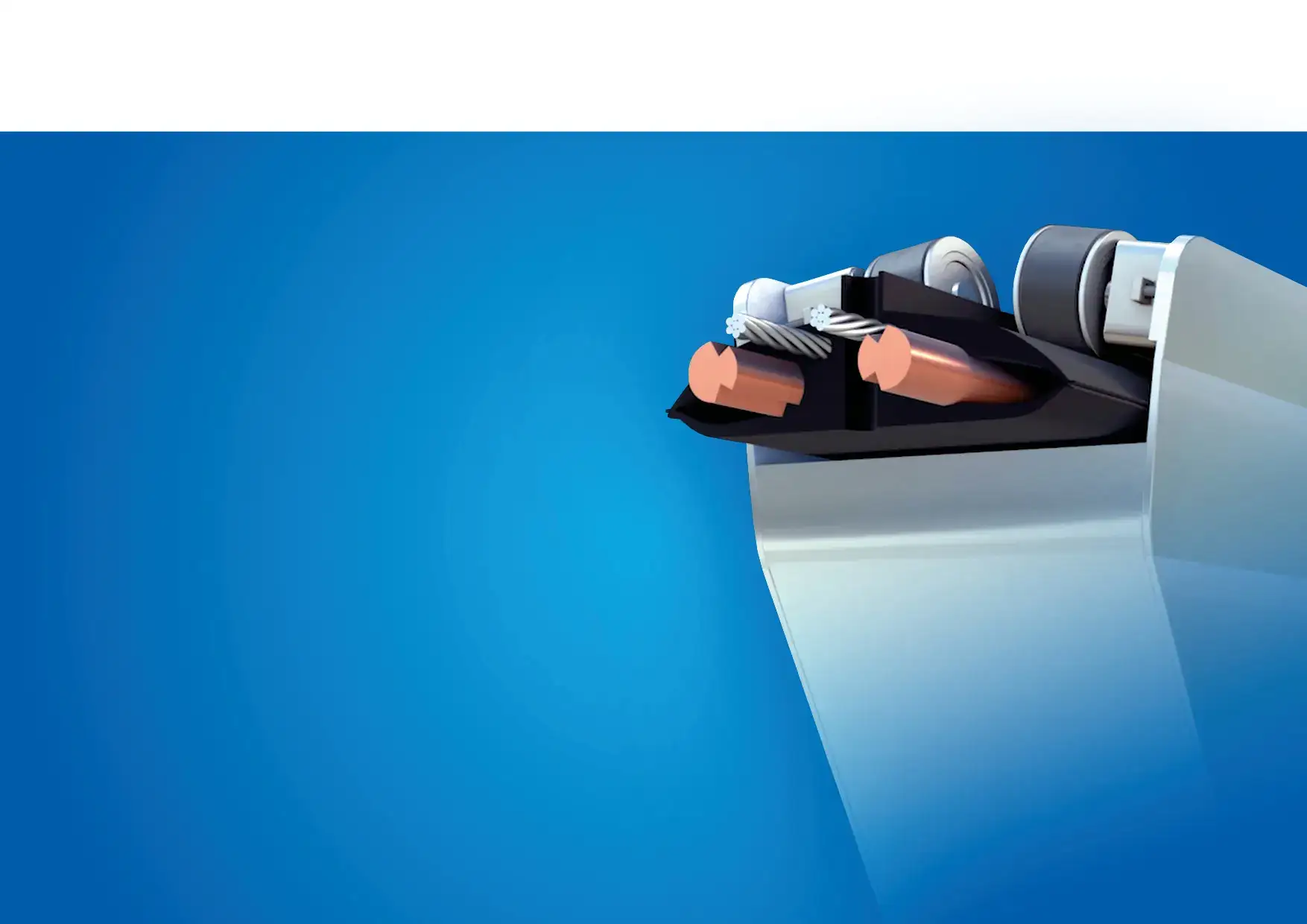
Motion starts with energy
Flexible cableMoving power collection
One planned route
The T-wire system combines a flexible electrical cable with a current collector trolley that travels along it, supplying electrical power to equipment that needs power while moving.
We are developing a power supply solution for mobile machinery, vehicles and equipment. We have built a model, conducted functional tests and documented the next stages of development.
A working model.
A foundation for further development.
We have a T-wire system model comprising the cable, current collector trolley and power supply, together with documentation of completed work and further development.
Model and functional testing
We developed the system concept and technical requirements for its components. We built a system model and carried out functional tests described in the project documentation.
TRL 5 achieved
We have achieved Technology Readiness Level 5 (TRL 5), as confirmed by the project documentation. The recordings below show the model on a test rig.
System development and demonstration
Further work includes building prototypes of the cable and trolley, testing the remaining components, including AI control and communication safeguards, and building a complete demonstration installation.
Eight application areas
One technology.
Different environments.
Choose an area to explore its configuration, potential benefits and next steps in testing.
Public transport and rail
Power for vehicles operating on regular routes.
Explore this application →
Industry and construction
Machinery, welding equipment and movable lighting.
Explore this application →
Surveillance and security
Moving observation stations and sensors.
Explore this application →
Tethered drones
A moving power point for observation and inspection.
Explore this application →
Material transport and cableways
Transport carts, gondolas and planned routes.
Explore this application →
Filming and events
Cable cams, cameras and lighting in motion.
Explore this application →
Solar farm maintenance
Power for mowers, washers and cleaning equipment.
Explore this application →
Mining
Mobile equipment in open-pit and underground mines.
Explore this application →The completed model and reported TRL 5 relate to the underlying T-wire technology. This does not mean that every application described has been tested. Sector-specific integration is a further development step.
A fixed route.
A moving current collector.
Three elements in the power path: the supply line, the current collector trolley and the connected equipment.
How does T-wire work?The cable defines the line
The supply line runs along the equipment's route. Its configuration is selected to suit permanent or temporary infrastructure.
The trolley collects power
The moving trolley interacts with the cable. The design provides local access to the conductors at the collection point.
Equipment operates in motion
The trolley supplies power to the equipment and positions itself in relation to it. The equipment can operate beyond the area directly beneath the cable.
How does power reach
the equipment?
Three views of the system: the power path, the moving collection point and the layout of the supply line.
01 / Power transfer chain
From the power source, through the cable and trolley, to the equipment.
02 / The collection point moves
The electrical contact area moves with the trolley.
03 / A line adapted to the route
Connectors, curves and junctions are selected to suit the installation layout.
Functional diagrams based on T-wire materials. Simplified and not to scale; these are not construction drawings.
From the cable
to a complete installation.
We configure the installation to suit the route, the equipment and the control method.
Flexible cable
A multicore cable designed for linear power collection.
Current collector trolley
A guidance and current collection mechanism that travels along the cable.
Connectors and junctions
Curves, connections and crossings that enable the installation route to be designed.
Control systems
Control systems for the trolley and other components, tailored to the task.
From the cable cross-section
to equipment in motion.
The full animation shows the design and interaction of T-wire components. Video with audio and English subtitles · 3 min.
This material is illustrative and does not constitute a technical specification or installation instructions.
Power that matches
your workflow.
Continuous power
The aim is to supply power while equipment is moving and reduce downtime associated with charging.
Less reliance on batteries
Direct power collection from the line may reduce the need for onboard energy storage.
Flexible configuration
The cable, trolley and route components form a system configured for the particular equipment and operating environment.
From design
to testing in motion.
Further development of the model includes testing individual components and the complete system: mechanical interaction, power collection and control. The planned scope of work is outlined below.
Mechanics and materials
Cable and trolley geometry, guidance characteristics, speeds, acceleration and resistance to motion.
Electrical connections
Interaction of current collection components, cooling, and reduction of voltage spikes and sparking.
Route and control
Travel through connectors, curves and junctions, and control of the trolley and auxiliary components.
Demonstration and integration
Testing of the complete system, technical documentation and adaptation to the target application.
Directions for further research and development
The following concepts identify further areas of T-wire research. Their development requires separate technical validation and adaptation to the operating environment.
Heavy transport in cities
A concept for powering heavy vehicles travelling through urban areas, without local exhaust emissions during electrically powered operation.
Ports and harbour channels
A concept for using the system during vessel manoeuvring and docking.
Airport ground operations
A concept for using the system to move and position aircraft within an airport.
Protecting T-wire technology and brand
Publications of the Polish Patent Office describe the cable design for linear current collection and the associated current collector trolley separately.
Flexible multicore power cable
Application P.432150 of 9 December 2019 — a cable design for linear current collection.
Polish Patent Office publication · WUP 9/2022Trolley collecting power from the cable
Application P.432151 of 9 December 2019 — a moving trolley for collecting power from a flexible cable.
Polish Patent Office publication · WUP 28/2021T-wire trademark
Certificate of registration of the T-wire European Union trademark. Registration date stated in the document: 25 June 2021.
Open registration certificate (PDF) ↗More about T-wire.
FAQ
Is T-wire a wireless power supply?
No. It uses contact-based power collection from a cable. A moving trolley connects the supply line to the equipment.
Does the equipment have to move directly beneath the cable?
The current collector trolley travels along the designed cable line. The equipment itself does not need to be located or move directly beneath the cable: the trolley positions itself in relation to it. The equipment's range of movement depends on the system configuration and its connection to the trolley.
Does the system replace batteries entirely?
Reducing battery capacity or eliminating batteries is one of the project's objectives. Whether this is possible depends on the equipment, its operating pattern and backup power requirements.
What voltages, power ratings and operating speeds are supported?
The system is designed to accommodate various DC and AC supply configurations. Cable cross-section is one of the parameters selected to suit the load and operating conditions; cross-section alone does not determine the type of current or voltage. Power supply parameters and travel speed require the entire system to be configured for the particular application.